Scr Motor Control Circuit Diagram
24+ Scr Motor Control Circuit Diagram Pictures. Motor control circuit is isolated by optocoupler and uses a triac with snubber circuit (c4, r14). Scr dc motor speed control circuit using ic cmos.
Ac voltage controller circuits have many applications in industry like tap changers in transformers, induction heating, speed control of induction motor and lights control.
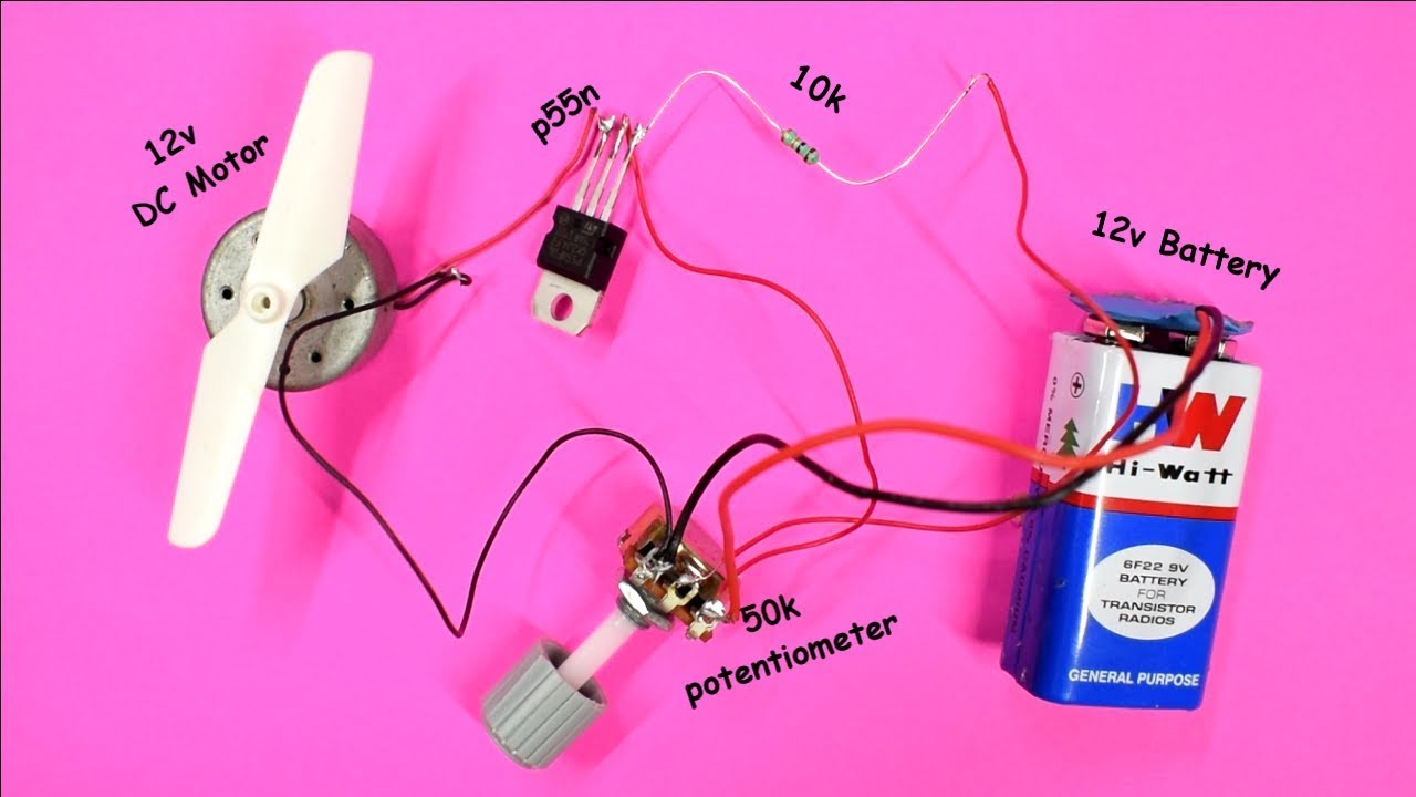
The speed of the motor can be controlled by changing the setting of p1 potentiometer. You can also add an led via a 1k resistor to indicate the state of the the finished remote control car! This page contain electronic circuits about motor control circuits at category motor control circuit : All control circuit components are shown as directly as possible, between a pair of vertical lines representing the control power supply.

0 Response to "Scr Motor Control Circuit Diagram"
Post a Comment